
At Dexter we are the magnet industry’s leading provider of custom magnetic couplings. We offer three types of couplings: synchronous, eddy, and hysteresis.
A magnetic coupling is a device that is capable of transmitting force through space without physical contact. Attractive and repulsive magnetic forces are harnessed to perform work in either a linear or rotary fashion.
About Magnetic Couplings
In its simplest form, a magnetic coupling is comprised of two components: a driver and a follower.
The driver is the portion of the mechanism connected to the prime mover (motor). Through magnetic interaction, the follower reacts to the motion of the driver, resulting in a non-contact transmission of mechanical energy. This non-contact power transmission has multiple benefits:
- Isolation of Components, which minimizes or eliminates mechanical vibrations through magnetic damping and allows for the insertion of a mechanical barrier between the driver and follower to separate environments and allow operation under pressure differentials.
- High Tolerance of Axial, Radial and Angular Misalignment between the prime mover and load.
- Allowance of Speed Variation and Regulation between the prime mover and load.
Quick-Turn Prototyping for Magnetic Couplings
Prototyping for your coupling is a critical step to ensure the magnetic solution meets your needs and requirements. At Dexter, our rapid prototyping service combines deep expertise and ingenuity with dedicated equipment to get you what you need in the time frame you need it.
Orders for custom couplings progress through two stages: feasibility and engineering.
In the feasibility stage, we work with you to discuss necessary design/manufacturing information (if an NDA is required for information transfer, one will be initiated). At the end of the feasibility phase, you will have an understanding of the technical suitability and estimate of costs.
If the estimates provided in the feasibility study are suitable, a formal quote will be created for you that includes engineering fees (sometimes assessed before starting the design process). The design process is interactive and will involve regular communication with our engineers to assure conformity to your needs.
After the feasibility process, we will create and internally test prototypes for conformity to dimensional specifications and force/torque requirements.
Contact us to learn more about magnetic couplings and our quick-turn prototyping service.
Synchronous (Class 1)
As the name implies, this coupling is a synchronous version that inherently results in a 1:1 relationship between the motion of the driver and follower. As taught in grade schools, like magnetic poles (North-North and South-South) repel each other while opposite poles (North-South) attract, synchronous couplings exploit these “attractive” and “repulsive” characteristics to produce motion. By placing an array of alternating pole permanent magnets (N-S-N-S) on the driver and an equivalent array of alternating pole permanent magnets on the follower, a “coupled” magnetic circuit is produced with each North and South pole in the driver linked to each respective South and North pole of the follower.
As the driver moves with respect to the follower, the magnet poles start to overlap one another, leading to a “push-pull” effect and consequent motion. The magnitude of the resultant force depends not only on the amount of overlap, but also on the chosen magnetic material’s characteristics and separation distance between the driver and follower.
At some displacement, however, the peak force producing capabilities of the coupling are achieved. Displacement beyond this point results in a decoupling. This decoupling manifests itself as a ratcheting action resulting from like magnetic poles is the driver and follower repelling each other. Unlike its mechanical equivalent, however, the decoupling does not, generally, lead to permanent damage; and synchronization is reinitiated at the next magnetic pole coupling point.
Pros: Greatest volumetric force density.
Cons: Limited to a 1:1 motion ratio
Use: Devices that require direct coupling with no slip during operation.
Eddy Current (Class 2)
This coupling is an asynchronous version that relies on a speed mismatch between the driver and follower to produce a force. An array of alternating pole permanent magnets (N-S-N-S) is placed on either the driver or follower, and an electrically conductive material (typically aluminum or copper) is placed on the mating component.
When the driver is translated with respect to the follower, an electrical current is induced in the conductive material, which results in a magnetic field that opposes the permanent magnets and “couples” the two components. Amperes Law governs the relationship between the induced electric and resultant magnetic fields. The magnitude of the resultant force is directly linked to the:
- Speed differential between the two components
- Magnetic material characteristics
- Resistivity of the conductive media
- Separation distance between the driver and follower.
Unlike the Synchronous Coupling (Class 1), this asynchronous version is a “lossy” device and prone to Ohmic loss heating resultant from the induced electric fields.
Pros: Speed mismatch between driver and follower.
Cons: “Lossy” – may require active cooling, reduced volumetric force density
Use: For asynchronous motion or force/torque changes as a function of speed (braking devices)
Hysteresis (Class 3)
As a hybrid of the Class 1 and Class 2 technologies, this coupling is typically used in an asynchronous fashion as a force limiter, but can be utilized in a synchronous state. An array of alternating pole permanent magnets (N-S-N-S) is placed on either the driver or follower, and an easily magnetized/demagnetized material known as Hysterloy is placed on the mating component. At rest, the permanent magnet array is designed to magnetize the Hysterloy, resulting in a synchronously coupled magnetic circuit*. Should these forces suffice for the application, this coupling will operate in a synchronous state.
*The volumetric force density can be orders of magnitude lower than the Class 1 coupling due to the magnetic characteristics of the Hysterloy.
However, should the prime mover induce forces in excess of this synchronized operating state, the driver decouples from and begins to move with respect to the follower. This motion causes the Hysterloy to cycle through its magnetization loop (magnetize-demagnetize-magnetize) via the permanent magnets on the mating component which are now translating with respect to it. Like the Class 2 eddy current coupling, the magnetic field from the permanent magnets is being utilized and converted. However, unlike the eddy current coupling where the energy from the magnetic field is converted to a flowing electrical current (and heat), the cyclical progression around the Hysterloy’s magnetization loop (hysteresis loop) utilizes the magnetic energy to convert the magnetization state of the Hysterloy material from a North pole to a South pole. As a result of this variant on the energy conversion mechanism, hysteresis coupling are much less prone to (although not completely excluded from) Ohmic heating.
Unlike the fully synchronous coupling which experiences a “ratcheting effect” when it exceeds its synchronous force threshold, this coupling continues to operate smoothly at asynchronous speeds while maintaining the force threshold. This is accomplished without the Ohmic heating inherent to the Class 2 coupling. Consequently, this Class 3 coupling provides a synchronous solution that can be decoupled and operated in an asynchronous state.
Pros: No ratcheting in asynchronous operating state and minimal heating during asynchronous operation.
Cons: Low volumetric force density. Limited sizes of Hysterloy materials.
Use: For asynchronous motion or force/torque limitations such as bottle cappers and tensioning devices.
Types of Couplings
Magnetic couplings are capable of transmitting forces both linearly and rotationally. Consequently, in addition to selecting the Class of coupling required (synchronous, eddy current, or hysteresis), the coupling type also needs to be specified.
Two types of couplings exist, torque and linear. As their names imply, torque couplings are used to transmit forces rotationally while linear couplings are used to transmit forces linearly. As one might expect, each coupling type also has a variety of geometric topologies that can be utilized to meet the design intent. The details of these configurations are found below.
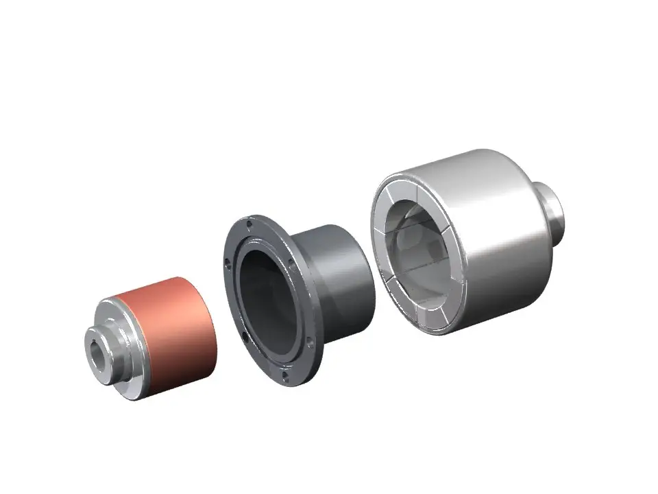
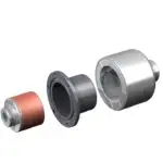
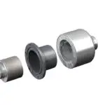
Torque Couplings – Coaxial
Coaxial magnetic couplings are configured so that one member of the coupling is fully nested within the ID of the second member. The two components share a common axis about which both rotate.
Axial misalignment – Very tolerant. In fact, it can easily be designed to accommodate very large axial misalignment if required.
Radial misalignment – Tolerant. The amount of tolerance is based on the spacing between the driver and follower. The larger the spacing, the greater the tolerance to radial misalignment. Large radial offsets in closely spaced coupling may lead to excessive radial loads on bearings.
Angular misalignment – Tolerant. The amount of tolerance is based on the spacing between the driver and follower. The larger the spacing, the greater the tolerance to angular misalignment.
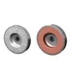
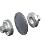
Torque Couplings – Face to Face
Face to face magnetic couplings are configured so that the magnetic flux is transferred about the flat end faces of the cylindrical assemblies. The two components are attracted to one and other axially, and typically require additional thrust bearing support for proper integration.
Axial misalignment – Mildly Tolerant. The amount of torque transmission is directly proportional to the axial spacing and number of magnets utilized in the design. Small variations in air gap may lead to large changes in torque
Radial misalignment – Highly Tolerant.
Angular misalignment – Tolerant. Due to the relationship between torque output and axial spacing, high angular misalignments may lead to unexpected reductions in torque
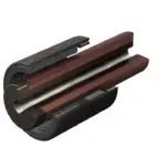
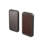
Linear Couplings – Tubular
Tubular magnetic couplings are configured so that one member of the coupling is fully nested within the ID of the second member. The two components share a common axis about which both translate.
Axial misalignment – Tolerant. Inherently, linear couplings align axially. As such, any misalignment will lead to the driver pulling the follower into position.
Radial misalignment – Tolerant. The amount of tolerance is based on the spacing between the driver and follower. The larger the spacing, the greater the tolerance to radial misalignment. Large radial offsets in closely spaced coupling may lead to excessive radial loads on bearings or shafts.
Angular misalignment – Tolerant. The amount of tolerance is based on the spacing between the driver and follower. The larger the spacing, the greater the tolerance to angular misalignment.
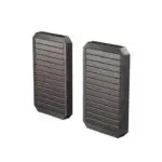
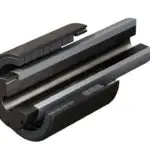
Linear Couplings – Planar
Planar magnetic couplings are configured so that the magnetic flux is transferred about the flat end faces of the magnetic assembly. The two components are attracted to one and other and typically require additional thrust bearing support for proper integration.
Planar (direction of motion) misalignment – Tolerant. Inherently, linear couplings align axially. As such, any misalignment will lead to the driver pulling the follower into position.
Planar (perpendicular to direction of motion) misalignment – Very tolerant. Designs can be produced to constrain 2-DOF if required.
Angular misalignment –Tolerant. The amount of angular misalignment depends on the air gap between the two members.
DESIGN HELP
- What type of coupling is required?
- Linear
- Torque
- What topology are you considering?
- Face-to-face (torque coupling)
- Coaxial (torque coupling)
- Tubular (linear coupling)
- Planar (linear coupling)
- How much force or torque would you like to transmit?
- What Class of coupling are you considering?
- Class I – Synchronous
- Class II – Eddy Current
- Class III – Hysteresis
- What speed will the coupling be traveling? (velocity or RPM)
- Is a barrier between the driver and follower required? If so, what pressure differential would you like the design to accommodate?
- Across what temperature range will this coupling operate?
- Are there corrosive elements or fluids that need to be taken into consideration? If so, what type are they?
- Geometric requirements:
- Driver
- Shaft size
- Mounting type
- Set screw and key
- Compression (threaded shaft end)
- Taper Lock (not available on all sizes)
- Max. OD
- Max. Length
- Follower
- Shaft size
- Mounting Type
- Set Screw and key
- Compression (threaded shaft end)
- Taper Lock (not available on all sizes)
- Max. Length
- Driver
- Bearing support (radial and axial) is typically provided outside of the coupling system, but can be accommodated in the design. Does bearing support need to be designed into the coupling?
- Is dynamic balancing required (for rotary systems)?
MATERIALS
MAGNETIC MATERIALS – Application dependent. Typically based on thermal and corrosion resistance requirements.
NdFeB – Temperatures up to 150°C. Corrosion protection required.
SmCo – Temperatures up to 350°C. Corrosion protection optional.
Ceramic – Temperatures up to 250°C. Corrosion protection not required.
Hysterlloy (Type III – hysteresis couplings) – Temperature up to 350C. Corrosion protection not required.
ELECTRICALLY CONDUCTIVE MATERIALS – Typically based on cost and size constraints.
Aluminum – Low cost. Moderate-high conductivity.
Copper – Moderate cost. High conductivity.
DRIVER AND FOLLOWER STRUCTURE – Application dependent. Typically based on corrosion resistance and cost constraints.
Cold Rolled Steels (1018, 1045, etc.) – Low-cost magnetic materials. Corrosion protection recommended. Low-moderate strength.
Alloy Steels (4140, 4340, etc.) – Low-to-moderate cost magnetic material. Corrosion protection optional. High strength.
Non-Magnetic Stainless Steels (316, 304, etc.) – Moderate cost. Corrosion protection not required. Typically used for hermetic sealed units. Low strength.
Magnetic Stainless Steels (416, 430, 17-4PH, etc.) – Moderate to high cost. Corrosion protection optional. Low-high strength dependent on heat treatment.
Nickel Super Alloys (Inconel, Hastelloy, Monel, etc.) – Very high cost. Very high strength. Corrosion protection not required.
Beryllium Copper – Very high cost. Very high strength. Corrosion protection not required.
Aluminum – Very low cost. Low strength. Corrosion protection not required.
BARRIER – Typically based on pressure and speed requirements.
Non-Magnetic Stainless Steels for moderate pressure and moderate speed applications. – Moderate cost. Corrosion protection not required. Low strength. Low electrical conductivity.
Nickel Super Alloys (Inconel, Hastelloy, Monel, etc.) high pressure and high speed applications. – Very high cost, Very high strength. Corrosion protection not required. Very low electrical conductivity.
Plastics (Nylon, Teflon, Delrin, super plastics, etc.) high speed, low pressure and precise force applications. Low to high cost. Low strength. Corrosion protection not required. Non-conductive.
Machinable Ceramics high speed, moderate pressure and precise force applications. Moderate to high costs. Low to moderate strength. Corrosion protection not required. Non-conductive.
FAQS
Please see our Magnetic Couplings FAQ in our Resource Center.