
Erasers (Bulk and Single)
EraseTrack™ Bulk Eraser
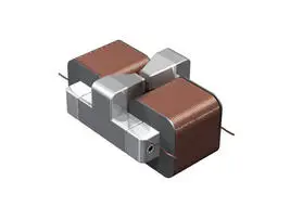
![]() Assisting disk producers to accelerate the slow process of servo erasing disk media, we have developed Dexter EraseTrack Bulk Eraser, a patented universal bulk disk eraser. Dexter EraseTrack can erase 25 disk cassettes faster that servo erasing a single disk. By combining its increased speed and capacity with a permanent magnet structure that does not require power or maintenance, Dexter EraseTrack provides disk producers with incredible process time savings.
Assisting disk producers to accelerate the slow process of servo erasing disk media, we have developed Dexter EraseTrack Bulk Eraser, a patented universal bulk disk eraser. Dexter EraseTrack can erase 25 disk cassettes faster that servo erasing a single disk. By combining its increased speed and capacity with a permanent magnet structure that does not require power or maintenance, Dexter EraseTrack provides disk producers with incredible process time savings.
Benefits:
- No electricity or maintenance required.
- No water cooling required.
- Can be easily integrated into conveyor system for final packaging and distribution.
- Permanent magnet construction provides no cycle time limitation due to heating or power supply constraints.
- Erases multiple disks in a single pass. Approximately 25 times faster than the servo erase process creating increased throughput.
Features:
- Designed to erase LMR & PMR disk media.
- 1 Tesla field (minimum) in erasure plane.
- Tilting mechanism for angle adjustment.
- Designed for 2-stacked longitudinal cassettes or a single cassette PMR.
- Cassette opening 5.4 inches in Y-axis, 10 inches in X-asis.
- Lifting hooks.
- Field outside box to be lower than 50 gauss, except at the gap opening where it can be close to 80 gauss.
- Constructed with clean room compatible materials.
- Warning labels for strong magnetic field.
- Approximate weight 5,800 pounds.


MATERIALS
Neodymium Iron Boron is used to create our EraseTrack™ designs.
DESIGN HELP
Although the Bulk Erase tool was designed for the rapid erasure or hard disk media, it can be utilized for any application that requires high magnetic field strengths (up to 2T) over large volumes. To initiate the magnetic design, a few characteristics must be defined:
- How strong of a magnetic field is required?
- How large of an opening is required? (width/height or diameter )
- How uniform must the magnetic field be? Over what volume?
- How will the unit be incorporated into your system? Is a stand/frame required? If so, what type?
These characteristics will help provide an idea of size for the system. Specific customer integration requirements are incorporated during the mechanical design stage of the process.
Single Erasers
Eraser Single Disk – Media Preconditioning
 Preconditioning with a write head is a slow process. For spin stand metrology, preconditioning with a head can be easily incorporated into existing tests. It complicates and lengthens the evaluation of read-write properties but is manageable. For drive builds, this can be a time consuming and costly process unless a wide write head is employed.
We can design and produce permanent magnet single disk erase tools to fully precondition media post sputter. Our magnetic material selection and circuit design expertise guarantees a device that meets magnetic field specifications within the physical limitation of existing or new equipment. In addition, our familiarity with HDDR devices and clean room compatibility requirements assures that the final device will be manufactured compliant to cleanliness and ESD specifications.
We have designed and manufactured devices for both PMR and LMR media that are successfully operating in production environments today.
Field strength is dependent on the physical size available for the device as well as gap requirements. In general, however, these devices can be designed to produce fields upwards of 1T on the media surface.
Types of Single Erasers
Perpendicular Media – New PMR media requires a specific field and leakage shape to guarantee proper conditioning without residual noise.
Longitudinal Media – LMR media requires a specific field and leakage shape to guarantee proper conditioning without residual noise.
Our experience with designing single disk erasers for this media type guarantees a quick turn around from concept to functional device.
DESIGN HELP
When working with our engineering group, you might be asked:
1. What type of media is being erased? a.) LMR b.) PMR
2. What erase field magnitude is required?
3. What size media is being erased?
4. What are the physical size constraints for the device?
MATERIALS
Electromagnets
- Copper Wire (insulation application dependent)
Permanent Magnets
- NdFeB – Highest Strength/volume, moderate cost., moderate temperature extremes (150°C),
- SmCo – High Strength/volume, highest cost, high temperature extremes (300°C)
- Ceramic – Low Strength/volume, lowest cost, high temperature extremes (300°C)
- Alnico – Moderate to High Strength/volume, high cost, highest temperature extremes (450°)
Frame Materials
- Nickel Plated Carbon Steels (1010, 1045) – high saturation flux, low cost, poor corrosion resistance
- Martensitic Stainless Steels (416, 430) – moderate-high saturation flux, moderate cost, good corrosion resistance
- Nickel Super Alloys (Hiperco®) – highest saturation flux, highest cost, excellent corrosion resistance
- Nickel Plated Aluminum – low cost, light weight
Headsetters
All magnetic materials are initially comprised of randomly oriented domains. The magnetization process rotates domains into common alignment and causes those aligned with the magnetizing field to grow in size. Full saturation would result in a single aligned domain if all anisotropy mechanisms can be overcome.
Practical magnetic materials have an internal self-demagnetizing field, which creates unfavorable orientations in magnetic domains near geometric extremities. Shorter magnets have a greater self-demagnetizing field (hence more unfavorably oriented domains) than longer ones. A high self-demagnetizing field effectively resets a material to its small domain, initial magnetization condition where Barkhausen response exhibits itself as noise. Step function domain alignment and growth cause Barkhausen noise in the initial magnetization phase.
MR sensors tend to be short in order to reduce track width and maximize areal density. This physical limitation typically results in units that have a high self-demagnetizing field and are subject to Barkhausen noise. To overcome this, an exchange bias film is deposited at the ends of the permalloy strip. Exchange coupling between the two films overcomes the self demagnetizing field of the sensing element, and supports a near single domain structure. Operating in this biased condition eliminates Barkhausen noise and maximizes magnetic response to signal inputs.
To develop the biasing field, the MR element must be initialized. The initializing field can come from an electromagnet or permanent magnet with inherent advantages and disadvantages for each. An electromagnetic field can be switched on and off, but power supplies and cooling can add to clean room costs. Permanent magnet assemblies can provide the required field intensities and uniformity, but they cannot be switched off and initial cost is usually higher.
For the electromagnet approach, we can design head setters that achieve magnetic field strength of up to 30 kOe (2.4MA/m). These electromagnetic head setters have low remnant field, are ESD proof, and clean room compatible. Thermal interlocks can be built in to shut off electric circuit in case the temperature rises above a preset threshold. Stray field can be shielded from magnetically sensitive devices in the proximity.A high magnetic field for initialization can be developed with a patented permanent magnet assembly produced by Dexter. Using rare earth magnets, our design is capable of generating gap flux densities as high as 30+ kOe (2.4 MA/m). The working gap field is greater than the residual induction of the magnet material. This is accomplished by superposition of magnetic fields of individual magnet segments. Features of this design are inherent flux straightness and uniform flux density in the gap, which are by-products of flux focusing. These features ensure tight control in magnetizing parameters.
Applications for head setters include read/write head manufacturing, MRAM and other magnetic memory devices and sensors.
DESIGN HELP
When working with our engineering group, you might be asked:
- What is the field strength required?
- What is the sweet spot required?
- What is the working gap?
- What is the clearance needed for the read/write head holder to bringing in and taking out the head?
- What is the envelope for the head setter?
- What is the remnant field requirement?
- What is the power duty cycle? Will the head setter be operating continuously?
- What is your power supply capability?
- What is the stray field requirement?
- Do you need reverse polarity capability?
- Do you need thermal interlocks built in?
- Do you need the head setter to be ESD (Electrostatic Discharging) proof?
- Do you need the head setter to be clean room compatible?
Alignment Magnets
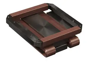

Alignment magnets are used to provide uniform fields across a substrate. These fields are used to coerce magnetically permeable materials into a preferred orientation. Alignment may occur either in process, or as a post process operation as is the case with annealing magnets.
Dexter has designed and built alignment magnets as small as 10 lbs and as large as 10,000 lbs. During the design, magnetic circuits of a specified topology are configured to precisely control the magnetic field shape, magnitude, and uniformity of the device. These output characteristics are all critical to the final performance of the product being processed.
To verify final performance, Dexter serializes and magnetically maps each device by making use of its 3D field mapping system.
The size of the magnet depends on the field requirements as well as the proposed system topology. Units as small as 10 lbs and as large as 10,000 lbs have been designed.
Types of Alignment Magnets
Annealing
Some products require post process orientation of grains in order to achieve full functionality. These post processes usually occur at elevated temperatures to allow granular motion. By exposing the product to a magnetic field while at elevated temperatures, the grains are free to align themselves with the magnetic flux lines. Keeping the product exposed to the magnetic field during the cooling cycle pins the domains in a preferred orientation. These types of magnets are typically external to the annealing oven, but can be placed within them utilizing proper material selections. These magnets can either be permanent, electromagnet, or superconducting depending on the field requirements and degree of adjustability required. Dexter’s expertise is in permanent and electro-magnets. Applications requiring superconducting versions are not supported. As such, fields in these devices are typically limited to 1 Tesla.
When used external to annealing ovens, thermal exposure must also be considered as significant heat can be transmitted from the oven to the magnet. Proper insulation or spacing of the magnet is recommended.
Electroplating
Frequently, Permalloy films are electroplated onto a wafer during the manufacturing process of read/write heads. Alignment of the Permalloy grains is critical to proper functionality of the final product. By exposing the wafer to a magnetic field while in the plating bath, the grains are free to align themselves with the magnetic flux lines. When removed from the plating bath, the film characteristics are pinned in a preferred direction of orientation
These types of magnets are installed external to the plating bath. These magnets can either be permanent or electromagnet depending on the field requirements and degree of adjustability required. Fields in these devices are typically limited to 1 Tesla.
As a result of the plating environment, these magnets can be exposed to corrosive elements. Proper plating and shielding of the magnets is critical to longevity of performance.
Sputtering
In process grain alignment of sputtered films can be critical to final performance of a product. During the thin film deposition process, magnetically permeable materials are deposited onto a substrate. If the sputtered atoms are exposed to a magnetically biased field during deposition, grain growth preferentially aligns with the magnetic flux lines. Upon solidification, the film characteristics are pinned in a preferred direction of orientation.
These types of magnets can be found either external to, or within sputter deposition system. These magnets can either be permanent or electromagnet depending on the field requirements and degree of adjustability required. Fields in these devices are typically limited to .1 Tesla.
As a result of the sputtering process, magnets located within the vacuum chamber typically require hermetic sealing to guarantee compatibility. Electromagnets found within the vacuum chamber typically require active cooling to assure thermal control over Ohmic losses that are occurring in the convection free environment.
DESIGN HELP
When working with our engineering group, you might be asked:
1. Is a permanent magnet or electromagnet solution preferred? If electromagnet, has a power supply already been selected? If so, what are its specifications (Power, Current, Voltage)?
2. What is the size of the volume or area you are looking to align?
3. What field strength do you required over that volume/area?
4. What field uniformity do you require over that volume/area?
5. What is the maximum skew required over that volume/area?
6. What are the maximum weight and size limitations of the magnet?
7. Will the alignment magnet be inside of a vacuum?
8. What temperature range will the alignment magnet work within?
9. Will the alignment magnet be submersed in a fluid?
10. How will the alignment magnet be integrated into your system?
11. How will the alignment magnet be integrated into your system?
- Beneath/above a tank or oven
- If beneath/above, how high or below the active volume/area?
- Around a tank or oven
- If around, what size vessel must the magnet accommodate?
MATERIALS
Electromagnets
- Copper Wire (insulation application dependent)
Permanent Magnets
- Nd-Fe-B – Highest Strength/volume, moderate cost., moderate temperature extremes (150°C),
- Sm-Co – High Strength/volume, highest cost, high temperature extremes (300°C)
- Ceramic – Low Strength/volume, lowest cost, high temperature extremes (300°C)
- Alnico – Moderate to High Strength/volume, high cost, highest temperature extremes (450°)
Frame Materials
- Carbon Steels (1010, 1045) – high saturation flux, low cost, poor corrosion resistance
- Martensitic Stainliess Steels (416, 430) – moderate-high saturation flux, moderate cost, good corrosion resistance
- Nickel Super Alloys (Hiperco®) – highest saturation flux, highest cost, excellent corrosion resistance