
A Combination of Magnetic Testing & Magnetic Inspection
Dexter’s Mission
Dexter applies outstanding quality, advanced manufacturing, and innovative magnetic designs to enable customer success and growth of our organization.
In order to provide the utmost quality, ensure advanced manufacturing, and develop innovative magnetic designs, Dexter has a wide range of magnetic testing capabilities. Measuring magnets and assemblies can be critical to quality and provide your application with improved accuracy, precision, and performance.
What is Magnetic Testing?
Magnetic measuring through testing is a way to determine the viability or magnetic effect of a magnet or assembly. Common magnetic tests may include torque testing, motor constant test, and a pull force test. Tests could be used to determine the performance of the device/magnet or even to determine its strength for safety.
What is Magnetic Inspection?
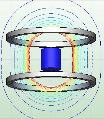
Magnetic measuring through inspection is the production of maps or images of magnetic fields in space using various inspection methods. Magnetic field mapping is an essential part of testing, verification, and troubleshooting of a magnetic device. It is needed for designing and optimizing of magnets and assemblies used in many applications such as particle accelerators, spectrometers (mass, nuclear magnetic resonance, and electron paramagnetic resonance), torque coupling; rotors; motors; oilfield devices; magnetic separation and dipoles for MRI. Depending on the applications, the magnetic field mapping can take place in 3D cartesian coordinates, in cylindrical coordinates, along a line, or at a point.
Magnetic Measuring Considerations
When performing magnetic measurements, there are multiple concepts to consider. Some are outlined below, however, please refer to our engineering team for advice. The magnetic inspection technique required may vary based on the need or application.
- Determining a measurement that represents your need
- Torque
- Force
- Magnetic strength
- Specifying a test limit
- Point values
- A line/shape
- Minimum and/or maximum field
- Be aware of surrounding magnetic impacts
- Stray magnetic fields
- Nearby magnetic materials (steel tables, steel support bars, etc.)
Magnetic Inspection Techniques
Dexter has obtained skills inspecting magnets that are quite broad and, in some cases, unique. Below are Dexter’s various tools outlined with their description, how we use them, and any notes we may deem important. The list is arranged from simple to complex tools.
Magnetic Viewing Paper

Description
A sheet comprised of tiny cells (each containing magnetic flakes within an oil) displays magnetic field patterns. Through this film/paper you can see the shape, location, and poles in a magnetic field. Poles appear dark and transition zones between North and South appear lighter in color.
Usage
Dexter commonly uses these to perform quick checks on magnetic assemblies and complex magnetic patterns. It demonstrates if the shape of the field is correct and if the assembly was properly executed.
Pole Indicator
Description
 |
 |
When the tip of a pole indicator is positioned on a magnet face, it will provide the polarity (North or South) of the magnet at that location.
Usage
This device is used to provide quick polarity checks on magnets and assemblies. Whether it is used in-process or post-process, it allows Dexter’s machinists and assemblers to ensure quality each step of the way.
Note
This measurement only provides polarity.
These devices are specifically created for pole indication. Using a compass is not advised as it is no the correct tool for identifying magnetic poles. A compass will show you South on a North pole.
When used for direction, a compass will always point towards North pole, but opposite poles attract. Therefore, the South end of a compass dial is what is actually pointing North even though it is painted North. If you place the North end of a magnet up to compass, the south end of the compass will face the magnet, and vice versa.

Fluxmeter and Helmholtz Coils
 |
 |
Description
A fluxmeter, when paired with a Helmholtz coil (or search coil) will provide a numerical measure of the overall output of a magnet. Imagine determining the magnetic output of the entire planet. The Helmholtz coil measures the magnetic moment of a magnet in a unit called Maxwell Turns. This measurement is determined by the movement of the magnet inside the coil influencing the voltage signal to the meter.
Usage
Dexter commonly uses HH coils to check that magnets are performing as expected. Magnets are commonly magnetized to full saturation (maximizes the output of what the magnet is capable of). After magnetizing, a magnet’s output can be immediately verified using a fluxmeter and HH coil setup.
Note
Each coil has a specific constant and produces a different value for Maxwell Turns. In addition, each coil has a size limit on the volume of magnet that can be tested inside.
Gaussmeter and Probes
 |
 |
Description
A gaussmeter when paired with probes produces a localized magnetic measurement. Gaussmeters work with various types of probes including axial, transverse, and gamma probes. The sensors in these probes are located in the tip of the device. The meter interprets the influence of the magnetic field on the sensor and converts it to measure either Gauss (US) or Amp/meter (Metric).
Usage
This device is used for various magnetic measurements. Since this provides a localized measurement, it can be used for measuring required strength in an assembly, from a distance, at a surface, etc. Dexter uses gauss probes (axial and transverse) to provide final checks or are used to check the field for calibration purposes. Gamma probes, on the other hand, are used to test large assemblies for approved shipment standards.
Note
Magnetic fields contain variation due to imperfections in the material. A surface that looks flat may not have a perfectly flat field shape.
When shipping magnets by air, there are regulations that prohibit how much flux leakage is permissible to be outside the shipping box/container.
Matesy M-Axis
 |
 |
Description
The Matesy machines Dexter has measure the magnetic moment of small magnets, similar to a Helmholtz coil, and can also measure the magnetic angle of a magnet (for strong magnets that have a specific direction). This angle measurement refers to the deviation angle between the physical axis and the orientation direction. The magnetic moment of a magnet is measure in Am^2 while the magnetic angle is measure in degrees. The magnetic angle can be identified within ±0.1° of deviation. Finally, the device can also identify a North or South orientation.
Usage
For applications that use very small magnets, but require a precise field, Dexter uses the Matesy to ensure quality magnets. Magnets tested on this device generally are a size that could fit on the tip of your finger.
Note
This machine is very sensitive and requires testing in an area that limits the amount of stray magnetic fields that could potentially alter its results. However, it’s this sensitivity that makes it so accurate for smaller magnets.
Also, note that some magnets are anisotropic with preferred orientation, but all magnets have a specific direction after magnetizing.
MagCam XYZ Scanner
 |
 |
Description
The MagCam is a magnetic field microscope that uses a “camera” cube with more than 16,000 hall elements on it’s 0.5”x0.5” face. On a 3-axis slide (with independently moving actuators), the machine can take surface and 3D images of a magnetic field to verify its shape. When the camera takes images of the field, it stiches all the measurements together to create a map. Sometimes, if the measurements are noisy, the camera is programmed to take multiple snapshots and average the data to provide a smoother result.
Usage
Dexter’s engineering team can program this device to be used for production assemblies or for inspection of prototype builds. The device is commonly used to verify magnetic field shapes and lines. While in the prototyping stage, confirming engineering’s designs is not only possible, but quick and easy. Data can be analyzed right at the machine or saved to be analyzed later.
Note
This machine can be programmed to perform specialized mapping and analysis.
Linear Mapping

Description
The Linear Mapper at Dexter is a custom and automated system that measures magnetic field along a straight line using a 3-axis probe. The probe can travel up to 30 inches along a straight line driven by a linear drive. The system is designed with a large aluminum table. And the linear drive is more than three feet away from the assembly being mapped. These design features keep magnetic objects away from the mapping region and reduces the measurement error.
Usage
Large magnetic assemblies or unique shapes are magnetically mapped with this system. The data is collected through a software terminal in an attached laptop. Commonly the assemblies mapped on this table are so large, they require the strength of multiple people to lift.
Note
This system was developed by Dexter for oil field devices. For these devices, the magnetic objects in the vicinity of the assembly can greatly impact the magnetic field.
Rotary Mapper
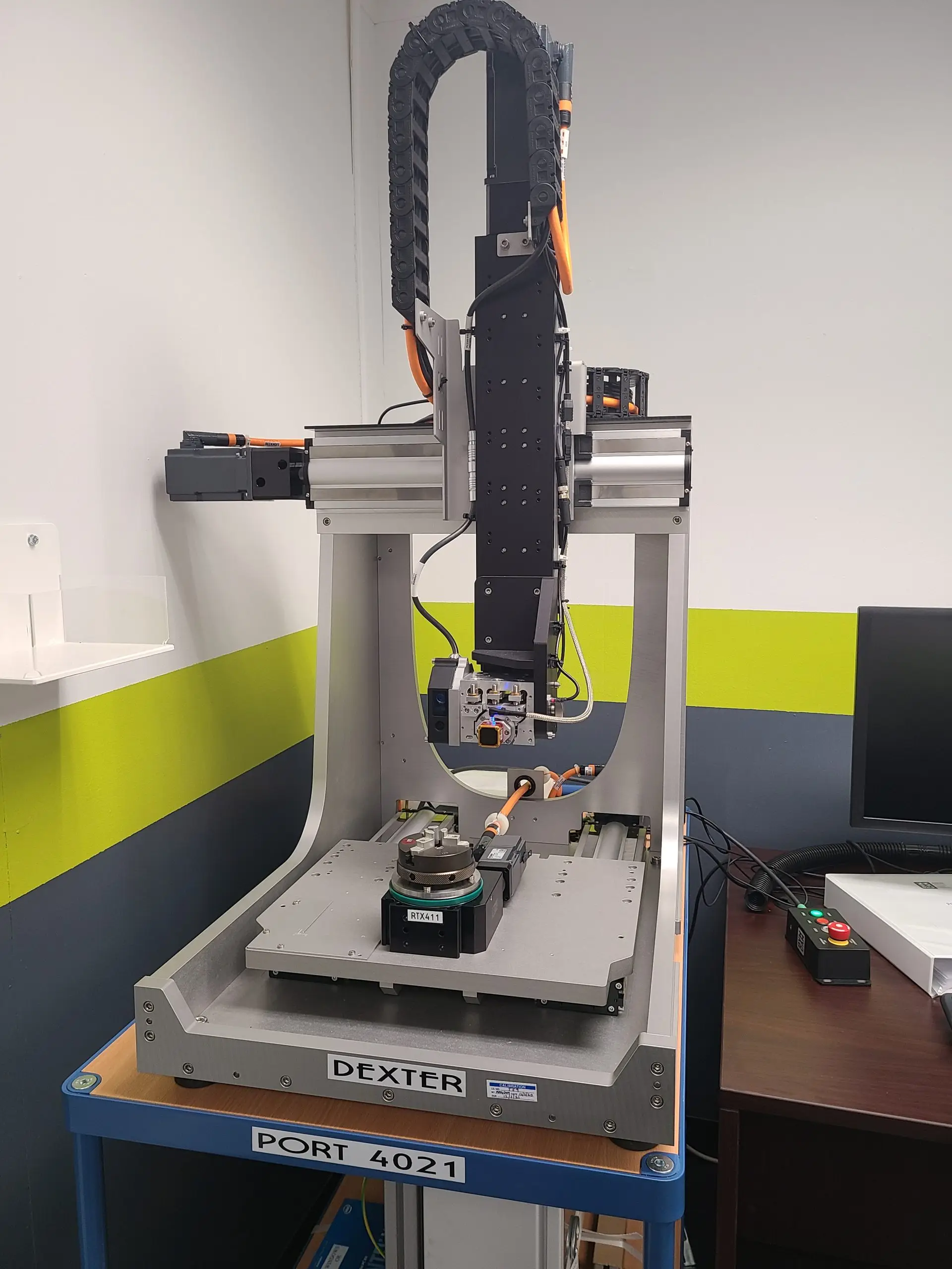

Description
The MagCam is a magnetic field microscope that uses a “camera” cube with more than 16,000 hall elements on its 0.5”x0.5” face, very similar to the MagCam XYZ Scanner. What’s unique about this device is that it can switch between a 3-axis mapping and a rotary mapping. Rotary mapping is capable when a motorized chuck is added to the measurement platform.
Imbedded on the device and in the program is also a laser scanner. The laser scan measures true distances to a radial edge or to the top of a device. This allows for true distance measurements to be used each time a part is scanned rather than relying on a calculated distance that does not accommodate variation between parts or assemblies.
Usage
Dexter’s engineering team can program this device to be used for production assemblies or for inspection of prototype builds. The device is commonly used to verify magnetic field shapes, lines, and profiles. While in the prototyping stage, confirming engineering’s designs is not only possible, but quick and easy. With the addition of a laser distance scan, data can be more reliable from lot to lot.
Note
When the camera takes images of the field, it stitches all the measurements together to create a map. Sometimes, when the measurements are noisy, the camera is programmed to take multiple snapshots and average the data to provide a smoother result.
Custom Testing Machines
Dexter has various custom designed testing machines or dedicated machines similar to the ones above. If your application requires a dedicated or custom device, please ask our engineering team about this. Other options include fixturing to test unique positions or locations. Whatever your application is. Dexter is committed to finding the best solution both in design and testing.